This part of the Ultra install guide covers the disassembly of the Ultra / G510 motor unit to make the new connections to the BAC855 controller. Please read the photos and text. If you click on the photo for each section you can load a video which will also show the step in more detail. Please take time to thoroughly read all the information. The hardest part is to ensure that the wiring does not get pinched and the bearing seals are seated correctly. Take your time and be patient. If you run into difficulties don’t get frustrated. Please get in touch for support via the Discord customer support system.
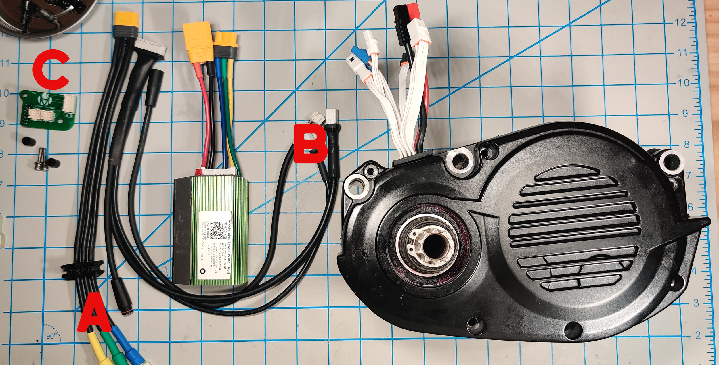
PRE Checks! - Make sure that you have the items in the picture. The kit parts you will need are the Phase wires and grommet (A), the main harness (B) and the circuit board, spacers and bolts (C).
Part 1 - CHECK YOUR MOTOR! - The HV Upgrade kit will only work on version 1.5. The latest CAN-BUS version starting to roll out to the market is currently not supported but we will be working to make a compatible kit in the future. The version you have is clearly indicated in the serial number that is located on the underside of the motor.
Part 2 - REMOVE THE MOTOR COVER - Remove the 6 screws (4mm Allen) from the cover. Lift cover off gently, careful to not tear the gasket if you don’t have a replacement. We can supply a TPU replacement gasket if you do run into issues at this point. Take it slow and you should have no problems. It is recommended that you have a small container to put the bolts in so you do not lose them!
** When you open the motor the gears can stick and pull out slightly. You will need to make sure they are seated before closing the motor.
Part 4 - CAUTION! - Sometimes the bearing washers fall out or stick to the bearing, be sure to lay them back into their bearing seat.
Part 5 - CAUTION! - Sometimes the alignment pins can fall out. Be sure not to lose these and make sure that they go back in the same position as before as they are essential to ensure that the motor assembles correctly.
Part 10 - Check that the circuit board looks like in the image here. The two spacers and bolts should be lined up correctly ready to make the harness connections.
Part 11 - You need to install the phase wires and the 12 pin JST connector to the BAC855 unit. You will also need to determine the correct length for your phase wires depending on where on the bike you are going to locate the BAC855 controller. Please see this tutorial if you are not familiar with crimping. ** Make sure the phase wires are inserted through the supplied sealing grommet before you crimp the terminals.**
The JST connector plugs into the circuit board and the phase wires are laid out as in the photograph and video. Getting the correct length on the phase wires is important as the room inside the case is quite tight.
Part 13 - Connect the Thermistor (two black wires) and Torque sensor (6 white wires) to the PCB. It is best to line up the motor like in the picture as the wire lengths are quite short. The thermistor and torque sensor use the same 6 pin connector. The connectors are labeled on the PCB so be sure not to mix them up.
Part 14 - Connect the Phase wire terminals. These go Blue to Blue, Yellow to Yellow and Green to Green! The lengths are quite short here so be careful not to pull on them while you make the connections. If they are not reaching then you may need to check you left enough length on the wire from the earlier steps.
Part 15 - ** This is by far the trickiest part of the process. The case should go together without force. It can be tricky to get all the parts lined up. If you are running into problems get in touch and we can give you some help.**
Carefully reinstall the cover onto the motor. Peak between the motor and cover before fully closing it to make sure none of the wires are going to get pinched. If needed, use your finger to help tuck the wires in and away from the edges of the housing and gears.
If the re-assembly is causing issues. Please check the following.
The bearing washers are aligned and seated properly.
The alignment pins are in and seated properly.
The rubber or paper gasket is lined up correctly.
None of the wires are being pinched.
The gears are properly seated into their bearings and in the motor case.
The most important thing is to be patient and take your time. Don’t get frustrated. Put it down. Give us a shout and we can link up with text, photo, video and chat and get things figured out!


